
Sure Fi Wiegand Manual
Doc #P10226 Rev 2.2
Table of contents:
- Quick Startup
- Part Numbers
- Overview
- Key Features
- General Specifications
- Radio Transceiver Specifications
- UL Information
- Device Overview
- Controller Interface connections
- Remote Interface connectors
- Providing Power
- Battery Backup Charging and UPS Functionality
- Power and Battery LED Diagnostics/Flash codes
- Jumpers JP1 and JP2 (REMOTE INTERFACE ONLY)
- Relays
- Wiegand Port
- Auxiliary Input/Output (AUX IN / AUX OUT)
- The Test Push Button (Range Test)
- LEDS
- Antenna
- Connectors
- Chain multiple system pairs for extended range
- Mounting
- Sure-Fi App
- Troubleshooting
- Wiring a Wiegand Device
- Wiring a Mag-Lock that is powered with a relay wet contact
- Wiring example for a Door Position Sensor
- RELAY 4 IN Remote Interface / RELAY 4 OUT Controller Interface
- Wiring a Door-Strike and a REX push button
- Wiring Example for Mag-Lock
- Wiring example for Gate Operator, REX, and Wiegand
- FCC and Industry Canada Regulatory Statements
- Warranty
Quick Startup

The two units that are packaged together are factory paired and will only communicate with each other.
Check initial operation
Connect a 9V battery (not included) to the 9V cable (included) and plug the two-position connector in to the Wiegand Controller and Remote Interfaces at the ‘12V’ and ‘GND’ positions on the bottom edge connector. Once both units are powered up, the green POWER LED should be ON steady on each unit. Press and quickly release the ‘TEST’ button on either unit to test communication between the two units. One or more of the blue LEDs should light up for one second to indicate that successful communication has occurred.
Perform a Range-Test from the desired install locations
With the 9V batteries plugged in to each of the units, place them at the desired install location points and perform a Range-Test by pressing and quickly releasing the ‘TEST’ button. The received signal strength is displayed for one second on the six blue LEDs with the bottom LED indicating the minimum signal strength and all six LEDs indicating maximum signal strength.
Connect to permanent power
Before connecting each unit to the permanent power source, ensure that it is a 12VDC supply that can source at least 1 ampere to the unit. Connect the power at each unit and perform several Range-Tests to check for adequate input power. If the green ‘Power’ and ‘Battery’ LED’s begin flashing in an alternating pattern, or if the unit resets, then an alternate 12VDC power source should be tried.
Wire the input and output functions
Using the wiring examples on pages 25 – 31 for reference, wire the required devices at each unit.

The maximum voltage that can be applied to any input or output pin (D0, D1, LED, AUX, R1IN – R4IN) is 5VDC.
Part Numbers
| DS004-BRIDGE | Wiegand Bridge system: includes 1 ea. DS004-CONTROLLER and DS004-REMOTE |
| DS004-CONTROLLER | Wiegand Controller Interface |
| DS004-REMOTE (REV2) | Wiegand Remote Interface |
Overview
The Sure-Fi DS004-BRIDGE Wiegand Bridge System consists of two units that are factory paired and ready to use out of the box with no configuration required. These units are the Controller Interface, Model DS004- CONTROLLER, and the Remote Interface, Model DS004-REMOTE. The system provides a wireless connection (bridge) from a remote location (door, gate, or relay device), to the controller location, such as an Access Control Panel. The Controller Interface wires to the Access Control Panel and communicates wirelessly to the Remote Interface, which is placed near any peripheral Wiegand device (card reader / keypad / receiver)and/or any relay/switch activated device. Each DS004-BRIDGE System consists of one Wiegand channel, two relay outputs and two relay inputs for functions such as door monitor sensors/request to exit inputs or any other relay-controlled function. Each unit has two relay outputs that correspond with the two relay inputs from the paired unit. The relays can be used independently and exclusively, meaning that it is not necessaryto use the Wiegand input to use the relays. The Sure-Fi App provides for configuration, diagnostics, and field firmware updates.
Certifications


Key Features
- Includes complete wireless solution from Remote location (reader/door) to Controller location
- Range: up to 1 mile through obstructions and greater than 50 miles line-of-sight
- Chain multiple system pairs for extended range
- One Wiegand port: compatible with Wiegand serial protocol up to 64 bit
- Two relay outputs per side NO, NC, COM terminals
- Two relay control inputs per side, i.e. Request to Exit input (REX), Door monitor input (DPS)
- One Auxiliary digital input/output (0 to 5V input/output)
- Backup Battery charger and UPS function
- DIN rail mount or direct wall mount
- Sure-Fi App connects via Bluetooth for diagnostics and firmware updates
General Specifications
| Operating Voltage: | 12VDC |
| Operating Current: | & 12VDC: 0.05A idle, 0.3A transmit. A 2A rated supply is recommended. |
| Operating Power: | 3.6 Watt (peak) |
| Battery backup: | 12V sealed lead acid (SLA) type only (12V/12AH for UL 294) |
| Battery Low Threshold: | < 11VDC |
| Battery Charge Voltage: | 13.75V maximum at standby charge |
| Battery Charge Current: | Trickle charge, 0.125A maximum at low battery voltage level |
| Relay Inputs (each unit): | Two relay control inputs: dry contact or digital 0 to 5VDC interface |
| Relays - Controller Interface: | Two Form C relays: 30VDC / 30VAC, 1A, 60W/ 125VA |
| Relays - Remote Interface: | Two Form C solid state relays: 30VDC / 30VAC, 1A || Max combined current 2A, Inductive |
| Relays - Remote Interface (Wet): | 10.42-12VDC special application, 1A Inductive (Logic, Relays JP1/JP2 and VBUS: 2A combined) |
| AUX Input/Output: | Input: dry contact or 0 to 5VDC interface. Output: 0V to 5VDC |
| Wiegand/Reader Power (VBUS) | Remote Interface VBUS: 10.7 - 12VDC special application, 0.75A |
| Range: | Up to 1 mile through obstructions. Greater than 50 miles line-of-sight |
| Encryption: | AES128 |
| Operating Temperature: | -40°F to +185°F (-40°C to +85°C), (0°C to +49°C verified by UL) |
| Storage Temperature: | -67°F to +257°F (-55°C to +125°C) |
| Humidity: | 0 to 85% non-condensing |
| Dimensions (L x W x H): | 3.54” x 4.23” x 1.28” (90mm x 107mm x 32.5mm) |
| DIN mount type: | 35mm DIN rail (DIN46277-3) / (DIN35) |
| Degree of Protection: | IP20 to IEC/EN 60529 |
Radio Transceiver Specifications
| Transmit Power: | 1 Watt (30dBm) |
| Frequency Band: | 902 – 928MHz |
| Channels: | 72 (Frequency hopping) |
| Receiver Sensitivity: | -133dBm |
| Link Budget: | 163dB |
UL Information
Table 1: UL Classification and Standards:
| Product Type: | Security Subassemblies |
| Product Covered: | USL, CNL: Model DS004-BRIDGE (includes one each of part number: DS004-CONTROLLER and DS004-REMOTE) To be installed in separately Listed enclosures. |
| Standard(s): | USL: UL 294 STANDARD FOR ACCESS CONTROL SYSTEM UNITS || CNL: CSA C22.2 No. 205 |
| CCN(s): | USL: ALVY || CNL: UEHX7 |
Table 2: UL 294 Performance levels
| Model | Destructive Attack | Line Security | Endurance | Standby Power |
|---|---|---|---|---|
| DS004-BRIDGE | 1 | 1 | 4 | 3 |
Table 3: System configuration:
| System Element | Description |
|---|---|
| Wiegand Bridge (part number: DS004-BRIDGE) | Wireless Link |
| Power supply | UL 294 or UL 603, power limited, power supply. || 12V,12Ah battery connected directly to the bridges. |
| Access Control Panel | Evaluated for Wiegand 26 bit |
| Access control reader (optional) | Evaluated for Wiegand 26 bit |
UL 294 installation requirements:
- Power to be provided by a UL 294 or UL 603, Listed, power limited/Class 2 12VDC power supply.
- All interconnected devices- access control unit, Wiegand devices, etc. to be listed UL 294
- Indoor use only in a protected area, 0 to +49C, 85% max non-condensing humidity.
- The DS004-CONTROLLER / DS004-REMOTE are UL listed subassemblies and are intended to be mounted in an enclosure as follows:
-
- Poly enclosure –UL Listed, Bud Industries, ‘POLYCASE’ YH-100806 or WH-18-02
- Conduit fittings: Mount conduit fittings in the areas shaded in green in Figure 1. Conduit fittings must not interfere or contact the battery or the aluminum backplate.
- Backplate – Use the aluminum mounting panel - 9.75 x 7.75 x 0.06 in. / 247.65 x 196.85 x 1.52 mm, secured to the provided screw holes of enclosure
- DIN rail – Mount DIN rail to backplate. Mount DS004-BRIDGE unit to DIN rail
- Tamper resistant screws to be used on enclosure
- Battery to be secured to prevent movement
- Battery wiring is not power limited and shall be secured with a minimum of 0.25” clearance from all other wiring
- Wire:
- 24AWG minimum wire size on any connection
- 90 feet maximum wire length on any connection
- Shielded cable to be used on any connection
- RSSI requires minimum of two blue RSSI LED’s (lower first two blue RSSI LED indicators) while performing a Range-Test (pressing the ‘Test’ button) to confirm UL 294 installation.
- Verify Firmware version 3.0 (UL 294 installation only): First, ensure that the unit is powered ON, then using the Sure-Fi App, connect to the unit by scanning the QR code, then press the ‘Advanced Settings’ button, follow the on-screen prompt to ‘Hold the Test button on the Bridge for 5 seconds’, then after seeing the ‘Status: Connected’ prompt, the Main Menu screen will show. To see the Firmware version, scroll down.
Instalation Standards:
- NFPA 70 – National Electrical Code, local codes, and the local authority having jurisdiction
- Manufacturer’s installation instructions
- CSA C22.1-02 – Canadian Electrical Code, Part 1, Safety Standard for Electrical Installations
- Local Authority having Jurisdiction.
Note: The following items not evaluated by UL:
- Firmware updating
- Sure-Fi App
- IP20
- AES128 Encryption
- Range: Range distances, RF output power not verified. Product testing performed in protected premises within the location of the access control equipment.
Device Overview
Figure 1: Sure-Fi bridge mounted in UL listed Polycase. Green shaded areas indicate where to place conduit fittings through case as to not interfere with the Sure-Fi bridge or the battery.
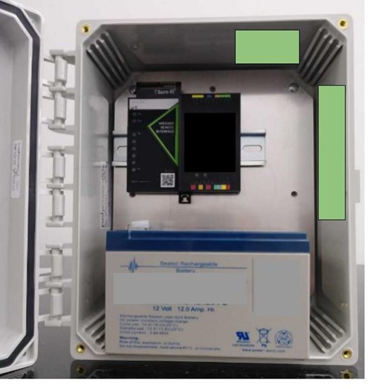
Figure 2: Overview, Wiegand Controller Interface
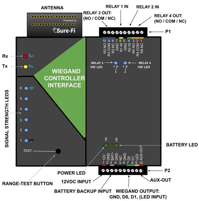
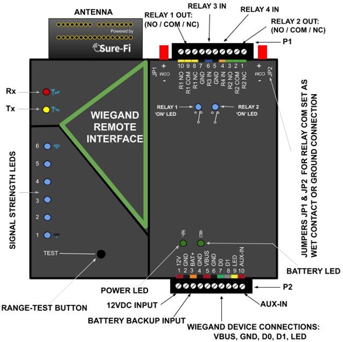
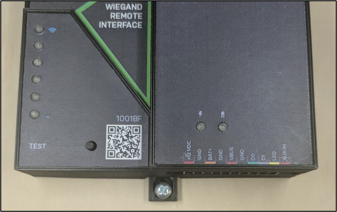
Figure 3: Overview, Wiegand Remote Interface
Controller Interface Connectors
Table 4: Top Edge Connector P1. See Figure 2 for connector location and pin numbers
| CONNECTOR | POSITION | NAME | DESCRIPTION |
|---|---|---|---|
| P1 | 1 (right end) | R4 NC | Relay 4 Normally-Closed terminal |
| P1 | 2 | R4 COM | Relay 4 Common terminal |
| P1 | 3 | R4 NO | Relay 4 Normally-Open terminal |
| P1 | 4 | R2 IN | Relay 2 control: activates Relay 2 on Remote unit |
| P1 | 5 | GND | DC Ground |
| P1 | 6 | R1 IN | Relay 1 control: activates Relay 1 on Remote unit |
| P1 | 7 | GND | DC Ground |
| P1 | 8 | R3 NC | Relay 3 Normally-Closed terminal |
| P1 | 9 | R3 COM | Relay 3 Common terminal |
| P1 | 10 (left end) | R3 NO | Relay 3 Normally-Open terminal |
Table 5: Bottom Edge Connector P2. See Figure 2 for connector location and pin numbers
| CONNECTOR | POSITION | NAME | DESCRIPTION |
|---|---|---|---|
| P2 | 1 (left end) | 12V | + DC input |
| P2 | 2 | GND | - DC input |
| P2 | 3 | BAT+ | Battery backup positive terminal ’+’ connection. 12V SLA type battery only. |
| P2 | 4 | GND | - DC input |
| P2 | 5 | NC | Not Connected |
| P2 | 6 | GND | - DC input (Wiegand Ground connection) |
| P2 | 7 | D0 | Wiegand D0 connection (5.0VDC maximum connection) |
| P2 | 8 | D1 | Wiegand D1 connection (5.0VDC maximum connection) |
| P2 | 9 | LED | Device LED connection (5.0VDC maximum connection) |
| P2 | 10 (right end) | AUX-0UT | AUX-OUT corresponds with input AUX-IN on the REMOTE INTERFACE. |
Remote Interface Connectors
Table 6: Top Edge Connector P1. See Figure 3 for connector location and pin numbers
| CONNECTOR | POSITION | NAME | DESCRIPTION |
|---|---|---|---|
| P1 | 1 (right end) | R2 NC | Relay 2 Normally-Closed terminal |
| P1 | 2 | R2 COM | Relay 2 Common terminal |
| P1 | 3 | R2 NO | Relay 2 Normally-Open terminal |
| P1 | 4 | R4 IN | Relay 4 control: activates Relay 4 on Controller unit |
| P1 | 5 | GND | - DC input |
| P1 | 6 | R3 IN | Relay 3 control: activates Relay 3 on Controller unit |
| P1 | 7 | GND | - DC input |
| P1 | 8 | R1 NC | Relay 1 Normally-Closed terminal |
| P1 | 9 | R1 COM | Relay 1 Common terminal |
| P1 | 10 (left end) | R1 NO | Relay 1 Normally-Open terminal |
Table 7: Bottom Edge Connector P2. See Figure 3 for connector location and pin numbers
| CONNECTOR | POSITION | NAME | DESCRIPTION |
|---|---|---|---|
| P2 | 1 (left end) | 12V | + DC input |
| P2 | 2 | GND | - DC input |
| P2 | 3 | BAT+ | Battery backup positive terminal ’+’ connection. 12V SLA type battery only. |
| P2 | 4 | GND | - DC input |
| P2 | 5 | VBUS | + voltage output for Wiegand device (See Figure 6) |
| P2 | 6 | GND | - DC input (Wiegand Ground connection) |
| P2 | 7 | D0 | Wiegand D0 connection (5.0VDC maximum connection) |
| P2 | 8 | D1 | Wiegand D1 connection (5.0VDC maximum connection) |
| P2 | 9 | LED | Device LED connection (5.0VDC maximum connection) |
| P2 | 10 (right end) | AUX-IN | AUX-IN corresponds with the output AUX-OUT on the CONTROLLER INTERFACE. |
Providing Power
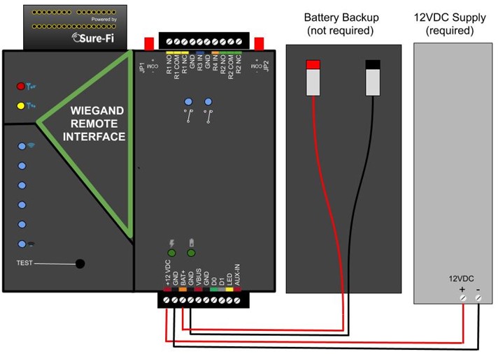
Each unit requires a 12VDC supply that is rated for at least 1A. If a Maglock, Door Strike, or other device is to be powered through an on-board wet relay, then the additional power required for those devices will need to be considered when selecting a power supply. A battery backup can be connected as shown if needed.
Figure 4: Backup Battery Connection
Battery Backup Charging and UPS Functionality
The Controller and Remote Interfaces both provide a charging voltage for a 12V sealed lead acid battery backup and they also have uninterruptable power supply (UPS) functionality. The UPS will automatically switch to the battery backup whenever the 12VIN wall power goes out and will then switch back to the 12VIN wall power when it returns.
Power and Battery LED Diagnostics/Flash codes
The two green LED’s that are labeled ‘POWER’ and ‘BATTERY’ are used to provide the status of the 12VDC input power and the Battery input voltage. The LED status information is described here:
Power Status: POWER LED (see note 1)
| LED STATE | DESCRIPTION |
|---|---|
| ON | Acceptable input voltage range. |
| Slow Flash (1Hz) | Detected input voltage is below 7VDC. Check for proper input voltage |
| Fast Flash (2Hz) | Detected input voltage is above 15VDC. Check for proper input voltage |
| OFF | No input power or device not functioning properly |
Battery Status: BATTERY LED (see note 1)
| LED STATE | DESCRIPTION |
|---|---|
| ON | Battery voltage normal |
| Slow Flash (1Hz) | Low battery voltage. Battery voltage is less than 11.0VDC |
| Fast Flash (2Hz) | Battery voltage high. Maximum Battery voltage is 13.8VDC |
| OFF | No battery connected: Detected battery voltage is less than 1VDC |
NOTES:
- The POWER LED and BATTERY LED will flash in an alternating pattern if the input voltage drops too low during a radio transmission and is an indication that the power supply being used is not able to source the required current transient during a radio transmission.
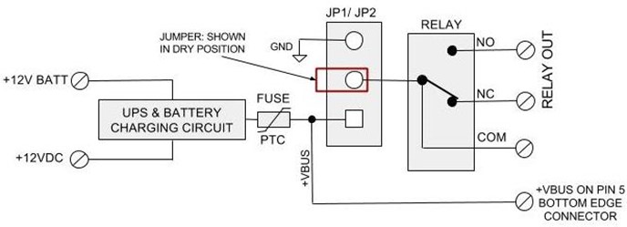
Jumpers JP1 and JP2 (REMOTE INTERFACE ONLY)
Jumpers JP1 / JP2 are used to connect the relay COM terminal to either GND or +VBUS. Connecting the jumper to the +VBUS creates a wet relay contact that can be used to source power to a device. JP1 is for Relay 1, JP2 is for Relay 2. Figure 5 shows the pinout of JP1/JP2. Use the supplied Jumper to connect the common terminal to either the – (GND) or the +(VBUS) pins if required for the desired Application. The + VBUS is the same voltage that is present on the power input at the +12VDC input, or if the Backup battery is in use, on BAT+. The Remote Interface is delivered with the supplied Jumpers on JP1 and JP2 set for a dry relay (COM not connected to either GND or +VBUS), see Figure 6.
Figure 5: JP1 / JP2 Pinout
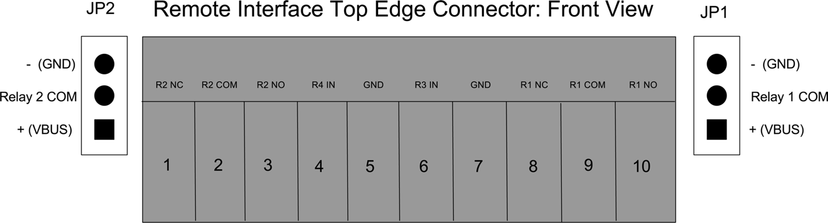
Figure 6: Diagram of Power Input, +VBUS, and JP1/JP2 functionality
Relays
Operating the relays
The relay outputs are operated by the corresponding relay inputs that are on the paired unit. For example, to activate Relay 1 on the Remote Interface, the Relay 1 input (R1 IN) on the Controller Interface must be shorted to ground (0VDC) using either a dry relay contact, a switch, or a digital voltage 0 to 5VDC interface. This can be tested by connecting a switch to the Controller Interface R1 IN and GND or connecting them to an access panel output relay NO and COM terminals. When the switch or the access panel output relay closes, the R1 IN will be put to GND (0V) and will cause the Relay 1 output on the Remote Interface to activate.
Relay In/out control
Relay 1 & 2 Outputs located on the Remote Interface: operated by R1 IN & R2 IN on the Controller Interface.
Relay 3 & 4 Outputs located on the Controller Interface: operated by R3 IN & R4 IN on the Remote Interface.
Wiegand Port
The maximum voltage that can be connected to the Wiegand D0, D1, and LED lines is 5VDC. Connecting a voltage higher than 5VDC can cause permanent damage.
Connecting Wiegand Port at the Remote Interface (see Figure 11)
Connect D0, D1, LED (if required) and GND from the Wiegand device to the Remote Interface. The power for the Wiegand device can be supplied from a separate supply or it can be supplied from the Remote Interface by connecting the ‘VBUS’ output to the power input of the Wiegand device. Before connecting power, ensure voltage compatibility and power requirements of the supply are adequate to power both the Remote Interface and the Wiegand device.
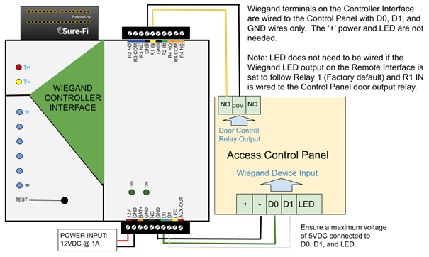
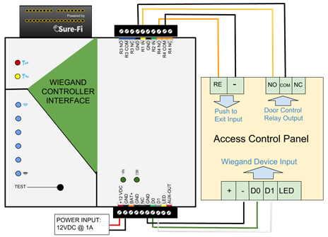
Connecting Wiegand Port at the Controller Interface (see Figure 12)
Connect D0, D1, and GND from the Controller Interface to the Wiegand input terminals of the control panel. The LED input does not need to be connected, see ‘Wiegand LED’ section below for more information.
Wiegand LED
The control of the Wiegand LED output is configurable using the Sure-Fi App. By default, the LED output at the Remote Interface follows Relay 1 which means that when Relay 1 is activated, the LED output will change states from an output-high (5V) to an output-low (0V) while Relay 1 is activated. Using the Sure-Fi App, the LED can be configured to follow either Relay 1 (default), Relay 2, or the LED input on the Controller Interface. With the default set at Relay 1, it assumes that Relay 1 is being used for the access entry point (Door Strike/Maglock/Gate Operator). When a valid credential is presented at the Wiegand device, the Access Panel will grant access by activating an Output relay that must be connected to the Relay 1 ‘R1 IN’ on the Controller Interface unit. When Relay 1 is activated at the Remote Interface the LED output changes to 0V which changes the LED color on the Wiegand device. With this default, the LED connection on the Controller Interface does not need to be connected to the access panel because the Wiegand LED follow’s Relay 1.
Auxiliary Input/Output (AUX IN / AUX OUT)
The Auxiliary input AUX-IN on the Remote Interface corresponds with the Auxiliary output AUX OUT on the Controller Interface. The AUX IN is interfaced in the same way as the Relay inputs, by shorting it to GND (0VDC) using either a dry relay contact, a switch, or a digital voltage 0 to 5VDC interface. When AUX IN is put at 0VDC, the AUX OUT on the Controller Interface will change states from a logic-high level (~5VDC) to a logic low level (0VDC).
The Test Push Button (Range Test)
Range Test: Pressing and releasing the ‘Test’ button quickly initiates the Range Test. The Range Test feature is used to test the signal strength of the radio transceiver with the paired unit and displays the results of a received transmission on the six blue LEDs, these are labeled ‘Signal Strength LEDS (1 – 6)’ in Figure 2. Maximum signal strength is indicated when LEDs 1 through 6 all flash ON and minimum signal strength is indicated when only LED 1 flashes ON.
LEDS
- POWER and BATTERY LEDS: these two LEDs provide power and battery input status information. See the ‘LED Diagnostics’ section for more information.
- Rx LED: The Rx LED will flash ON once briefly when a Sure-Fi radio transmission is received.
- Tx LED: The Tx LED will flash ON once briefly upon a radio transmission. The Tx LED will flash ON only on the unit that initiates the transmission.
- Relay 1 – 4 LED’s: The Blue LED’s on each unit below the Relay outputs will illuminate when the corresponding Relay is in the energized state.
Antenna
The radio antenna is created using copper traces on both sides of the PC Board. Use caution when handling and mounting the unit to ensure that no damage (scratches, etc) occurs to the PC Board/Antenna. Additionally, for best performance, keep cables and wiring away from the antenna and mount the unit oriented with the antenna upwards.
Connectors
The top and bottom connectors are 10-position, 3.5mm EURO type. The mating plug is Molex pn 39500-0010. Wire Range: 16 to 30AWG stranded or solid. Wire strip length 0.250”. Recommended screwdriver: slotted blade 0.98” (2.5mm) width. To install a wire, turn the screw counter-clockwise 3 or 4 turns, insert the wire and hold in place while tightening the screw. When complete, pull on the wire to ensure that it is tightened adequately.
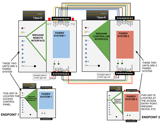
Chain multiple system pairs for extended range
If a single paired system is unable to communicate from the desired two endpoints, a second paired system can be used to create a ‘chain’ to extend the range. If required, many paired systems can be ‘chained’ together for extremely difficult installations. To accomplish this, each paired system in the chain is wired to another paired system to pass the signals between them (see Figure 7 for a wiring diagram).
Figure 7: Chained systems wiring diagram
Mounting
DIN Rail mount
DIN rail mounting allows the unit to easily clip and unclip from the DIN rail. Attach a piece (minimum 4” length) of 35mm type DIN rail to the wall and then snap the unit to the DIN rail or slide it on from the end.
The unit will snap in to place by putting the top retaining tabs on to the DIN rail first, then pressing the bottom on to the DIN rail until it snaps in to place, the bottom DIN clip may need to be pressed upward to seat into its locked position. To remove the unit from the DIN rail, use a small screwdriver, insert in to the bottom DIN rail clip and pull gently down and outward until the unit releases from the DIN rail.
Screw mount
The DIN rail clips on the base of the enclosure case can be snapped outward to allow for screw mounting of the case. Mount using only the single bottom DIN clip and the top DIN clip that is located on the side below connector P1. Do not use the DIN clip located behind the antenna. See Figures 8, 9, and 10.
If mounting the unit to metal, take note that metal shavings that are created can drop into the unit and damage the electronics. To avoid any metal shavings from dropping down in to the case, it is recommended to remove the top DIN clip completely from the base and secure it to the wall first, then slide the case on to the DIN clip. The second screw can then be secured through the bottom DIN clip without removing the clip. #8 self-drilling screws are recommended. Do not use any screw that is larger than a #8 size.
Figure 8: The two DIN clips are shown pressed outward and ready for screw mounting:
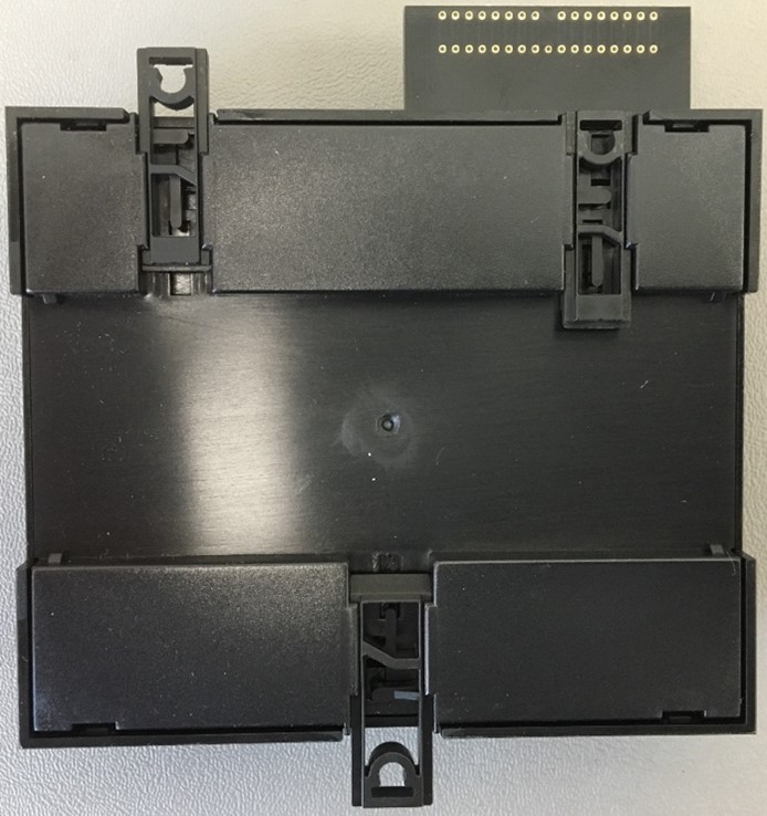
Figure 9: The top screw is shown mounted through the DIN clip to the wall:
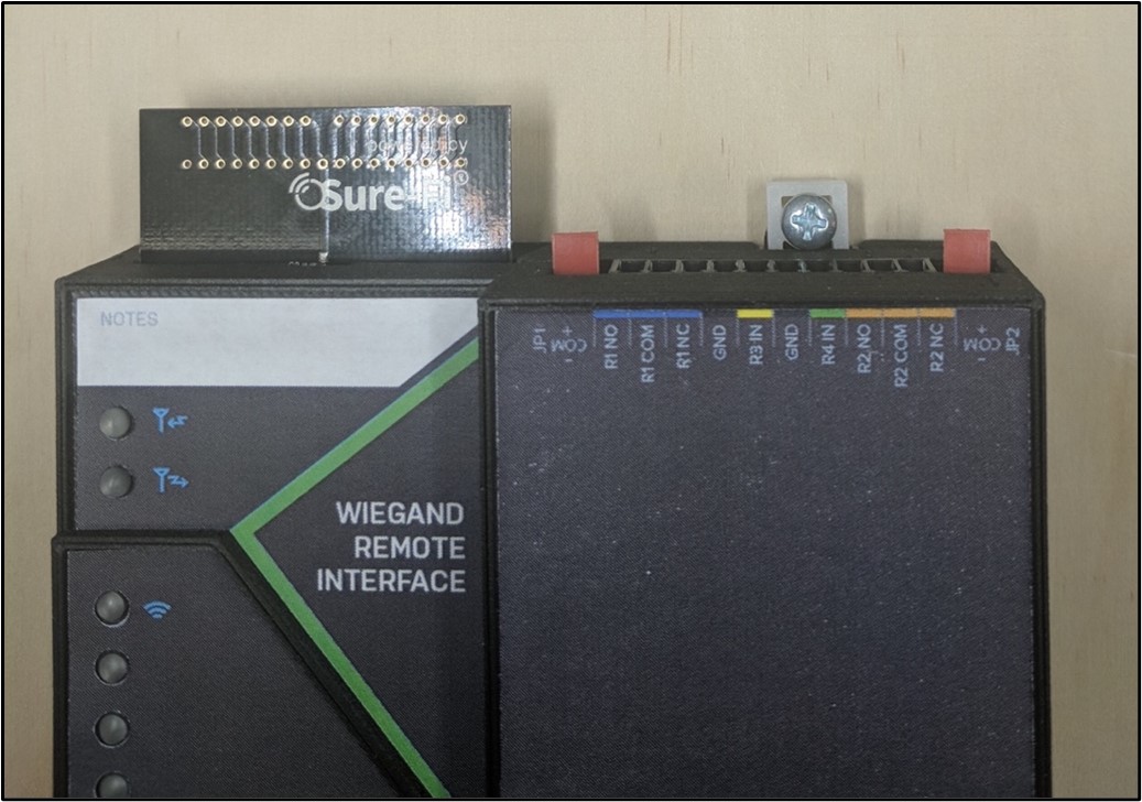
Figure 10: The bottom screw is shown mounted through the black DIN clip to the wall:
Sure-Fi App
The Sure-Fi App for iOS and Android allows for firmware updates, configuration and customization as well as for some diagnostics and troubleshooting information. The App is continually being updated to provide for more information and features and to improve its ease of use. To download, search for ‘Sure-Fi’ and then download and install. The key features of the App are:
- Configuration of the Wiegand LED output (default to follow Relay 1, can be set to Relay 2 or LED input)
- Configure the six Signal Strength LED indicators for ON/OFF, persistence time (default is ON, 1 second)
- Setting default Relay output values upon a set timeout interval (in increments of the Heartbeat time).
- Setting the system Heartbeat time.
- Diagnostics information / Troubleshooting (activates relays ON/OFF, etc)
- Access to documentation (Operators Manual, Application Notes, Reference documents, etc.)
- Field Firmware Updates (Firmware updates should only be performed if advised by Sure-Fi technical support)
Using the Sure-Fi App
Connecting
The Sure-Fi App uses the Bluetooth on the user’s phone to connect to the Bridge’s onboard Bluetooth interface. To use the App, be sure that the Controller or Remote Interface is powered ON, then open the App, then scan the QR code that is on the unit next the ‘TEST’ button. The Status will show ‘Connecting’, then after a pause it will say “Hold Test button on the Bridge for 5 seconds”. If the connection is successful, the status will show ‘Status: Connected’ and all the features of the App will be available for use.
Firmware Updating
Firmware updates must be completed on both the Controller and Remote Interface when updating the firmware of either side. The Bridge pair may operate erratically or be non-functional until both sides have been updated to a new firmware version. If updating firmware on one side, plan to immediately go to the other side and perform the same firmware update.
A data connection must be available on the device (phone) that the Sure-FI App is running on. Be sure that the App remains connected to the Bridge unit during the update process which usually takes a couple minutes to complete. After connecting to the Bridge unit with the App, select ‘Update Firmware’ from the menu. The ‘Update Firmware’ screen will show the current firmware versions and show if a newer released version is available. Select ‘Start Firmware Update” to begin the updating process. A notification will be given when the update is complete. When complete, close the App and then power-cycle the unit.
Configuration of the Wiegand LED
The default setting for the Wiegand LED is for the LED output of the Remote unit to follow Relay 1. The LED can be set to follow either Relay 2 or to follow the LED input on the Controller Interface unit.
Setting the System Heartbeat time
The system Heartbeat is the time interval when the system will automatically perform a system status check if there have not been radio communications between the units during that time. The Heartbeat timer is reset each time any successful transmission occurs between units during regular usage. The Heartbeat system status check verifies communication between units and that all output states correspond correctly with the given inputs. If a unit does not receive the Heartbeat, it will continue to attempt communications and it will keep all outputs set at their current state unless any of the outputs have been set for fail-safe values using the App. In that case, the unit will set the output values as configured when the set time interval is reached. The Heartbeat time interval and the number of Heartbeats that can be missed are configurable with the App.
Setting a Relay default state, timeout, and setting an Alert Relay
This feature is defaulted from the factory as disabled. With Relay default state disabled, the relays will remain in their current state during any time that communications with the paired unit are interrupted. The relays can be set to default as activated or deactivated after a set time interval has passed if communication with the paired unit is interrupted. The time interval is based on multiples of the Heartbeat time. When the time interval is reached, the relay(s) will go to the selected default state (activated or deactivated) as configured in the App and will remain in that state until regular system activity returns. This feature provides a way to define the relay default state if communications between units is interrupted for a period of one or more Heartbeat time intervals and allows for a way to have a relay to be set as an ‘Alert’ Relay to indicate RF communications interruption.
Troubleshooting
Testing Range and RF communications
Press and release the ‘Test’ button on one of the units and observe the six Signal Strength LEDs. If any of the blue LED 1 through LED 6 lights up momentarily then the transmission between the two units was successful. This establishes that the radio communications between the two units is operational and even with only the LED 1, there is adequate signal strength for proper function.
Wiegand data issues
If there is a problem with the Wiegand data getting through to the access panel, check the following:
- 1. Wire the Wiegand outputs (D0, D1, GND) from the Wiegand Controller Interface to the Access Panel.
- Wire the Wiegand device to the Wiegand Remote Interface and ensure that the Wiegand device is powered per the manufacturer’s specification.
- Test that the Wiegand device and the Access Panel are configured and functioning properly by connecting the Wiegand device directly to the Access Panel and then present a valid credential to the Wiegand device. Verify that the credential is properly accepted by the Panel and that the output relay on the panel is activating.
- At both Controller and Remote units, without any wires connected, measure the voltage on D0 and D1 relative to GND. This voltage should be between 3.2V to 3.5V on the Remote Interface and 5.0V on the Controller Interface. These voltages can vary slightly when D0/D1 are connected to a Wiegand device or the Panel Wiegand input. If the voltage is too low, external pullup resistors may be required. See Sure-Fi Application Note AN0135 for details on wiring the pullup resistors.
Wiegand cable runs
- If the cable-run from the Wiegand Device to the Remote Interface is longer than 48 inches, it is recommended to use a shielded cable. The shield wire should be connected to the Remote Interface GND terminal.
- Do not route the Wiegand data cable next to high voltage power (115/220VAC) lines.
For the best performance between the Controller and Remote units
- Power both units with their own dedicated power supply with a minimum of 1A & 12VDC.
- Route all cables and wiring away from the area near the Antenna.
- Avoid routing cables and wiring over the top of the unit.
- Mount both units oriented with the antenna at the top of the unit facing upwards.
- Rotating either (or both) of the units may provide an improvement in range.
- If additional range is required, avoid placing either unit on or near metal and place each unit at a higher location.
Manually Testing Relays
Each Relay pair can be manually tested to verify operation. Using a jumper wire, short the Relay input, such as R1 IN to GND, then monitor the Relay 1 OUTPUT on the bridge pair unit. This can be done on all four Relay inputs: R1 IN, R2 IN, R3 IN, and R4 IN. Remember, if testing the relays on the Remote Interface REV2 (DS004- REMOTE REV2), that the relays are solid state type and a ‘click’ will not be heard when these two relays activate and so a meter or device would need to be connected to verify relay activation.
Wiring a Wiegand Device
Figure 11: Wiring a Wiegand device to the Remote Interface
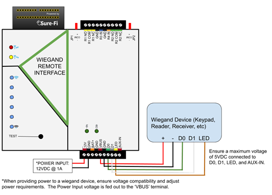
Figure 12: Wiring the Panel Wiegand port (and R1 IN & GND for LED operation) to the Wiegand Controller Interface
Wiring a Mag-Lock that is powered with a relay wet contact
Figure 13: Wiring a Maglock to Relay 1 NC as a wet contact on the Remote Interface
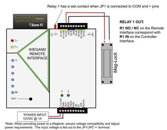
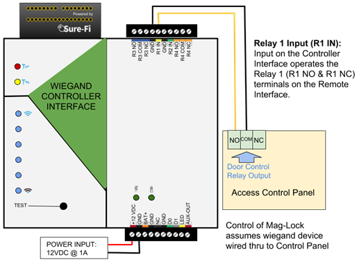
Figure 14: Wiring the Panel Door output relay to R1 IN & GND on the Controller Interface
Wiring example for a Door Position Sensor
Figure 15: Wiring a Door Position Sensor to R3 IN on the Remote Interface
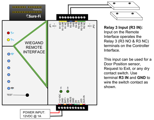
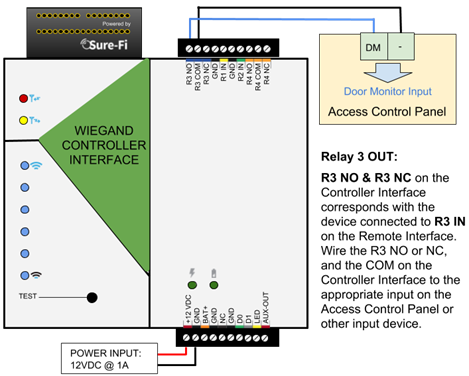
Figure 16: Wiring the Panel Door Monitor Input to R3 NO & R3 COM on the Controller Interface
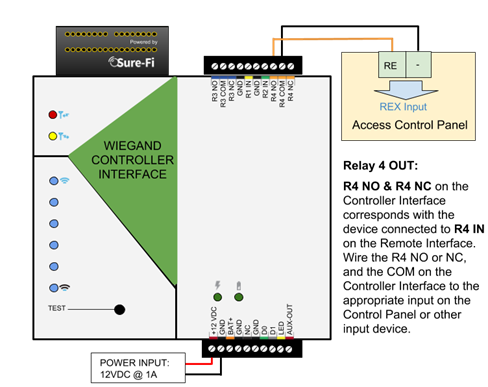
RELAY 4 IN Remote Interface / RELAY 4 OUT Controller Interface
Figure 17: Relay 4 IN wiring a Request to Exit button on the Remote Interface
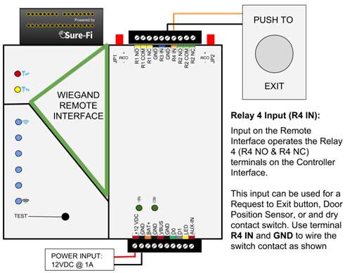
Figure 18: Relay 4 OUT Wiring at the Controller Interface
Wiring a Door-Strike and a REX push button
Figure 19a: REMOTE wiring of an externally powered Door-Strike (R1 NO), REX button (R4 IN), and Wiegand
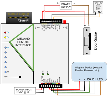
Figure 19b: REMOTE wiring of a Door-Strike powered by the Remote Interface (R1 NO), REX button (R4 IN), and Wiegand
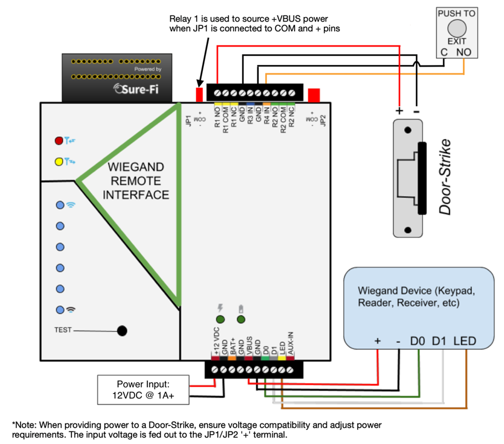
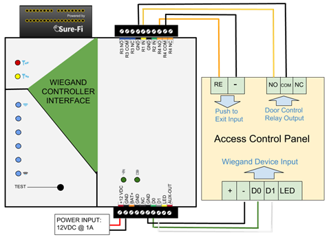
Figure 20: PANEL wiring for the Door Strike control (R1 IN), REX button (R4 NO), and Wiegand device
Wiring Example for Mag-Lock
Figure 21: REMOTE wiring for an externally powered Maglock (R1 NC), REX button (R4 IN), and Wiegand
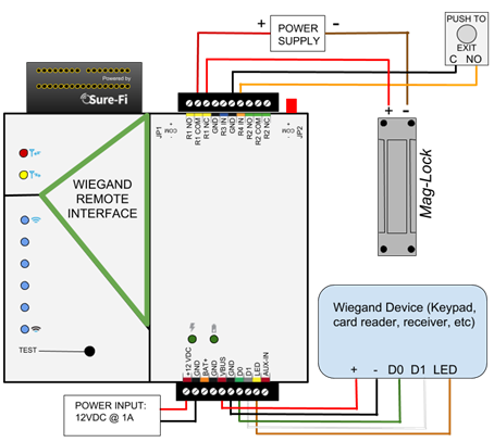
Figure 22: PANEL wiring for an externally powered Maglock (R1 IN), REX button (R4 NO), and Wiegand
Wiring example for Gate Operator, REX, and Wiegand
Figure 23: REMOTE wiring for a Gate Operator (R1 NO), REX button (R4 IN), and Wiegand device
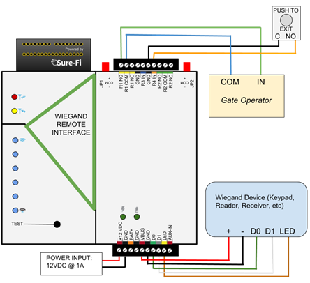
Figure 24: PANEL wiring for a Gate Operator (R1 IN), REX button (R4 NO), and Wiegand device

FCC and Industry Canada Regulatory Statements
FCC
This device complies with part 15 of the FCC rules. Operation is subject to the following two conditions: (1) This device may not cause harmful interference, and (2) this device must accept any interference received, including interference that may cause undesired operation. Any changes or modifications not expressly approved by manufacturer could void the user’s authority to operate the equipment.
IMPORTANT! Any changes or modifications not expressly approved by the party responsible for compliance could void the user’s authority to operate this equipment.
Industry Canada
This device complies with Industry Canada license-exempt RSS standard(s). Operation is subject to the following two conditions: (1) this device may not cause interference, and (2) this device must accept any interference, including interference that may cause undesired operation of the device.
Le présent appareil est conforme aux CNR d’Industrie Canada applicables aux appareils radio exempts de licence. L’exploitation est autorisée aux deux conditions suivantes: (1) l’appareil ne doit pas produire de brouillage, et (2) l’utilisateur de l’appareil doit accepter tout brouillage radioélectrique subi, meme si le brouillage est susceptible d’en compromettre le fonctionnement.
IMPORTANT! Tous les changements ou modifications pas expressément approuvés par la partie responsable de la conformité ont pu vider l’autorité de l’utilisateur pour actioner cet équipment.
47 CFR 15.105- FCC
NOTE: This equipment has been tested and found to comply with the limits for a Class B digital device, pursuant to part 15 of the FCC Rules. These limits are designed to provide reasonable protection against harmful interference in a residential installation. This equipment generates, uses and can radiate radio frequency energy and, if not installed and used in accordance with the instructions, may cause harmful interference to radio communications. However, there is no guarantee that interference will not occur in a particular installation. If this equipment does cause harmful interference to radio or television reception, which can be determined by turning the equipment off and on, the user is encouraged to try to correct the interference by one or more of the following measures:
- Reorient or relocate the receiving antenna.
- Increase the separation between the equipment and receiver.
- Connect the equipment into an outlet on a circuit different from that to which the receiver is connected.
- Consult the dealer or an experienced radio/ TV technician for help.
This Class B digital apparatus complies with Canadian ICES-003.
Cet appareil numérique de la classe B est conforme à la norme NMB-003 du Canada
FCC Radiation Exposure Statement
This equipment complies with FCC radiation exposure limits set forth for an uncontrolled environment. This equipment should be installed and operated with minimum distance 20cm between the radiator and your body.
Important Note:
Radiation Exposure Statement:
This equipment complies with IC radiation exposure limits set forth for an uncontrolled environment. This equipment should be installed and operated with minimum distance 20cm between the radiator and your body.
Note Importante: (Pour l’utilisation de dispositifs mobiles) Declaration d’exposition aus radiations:
Cet équipement est conforme aux limites d´exposition aux rayonnements IC établies pour un environnement non contrôlé. Cet équipment doit être installé et utilisé avec un mimimum de 20 cm de distance entre la source de rayonnement et votre corps.
Warranty
The warranty period of this product is 5 years from purchase date, beginning from first power up of the device after purchase. During this period, if the product does not operate correctly, due to a defective component, the product will be repaired or replaced at the sole discretion of Sure-Fi, Inc. This warranty does not extend to the product casing which can be damaged by conditions outside of the control of Sure-Fi, Inc.
EXCEPT AS SET FORTH ABOVE, SURE-FI, INC. MAKES NO WARRANTIES REGARDING THE GOODS, EXPRESS OR IMPLIED, INCLUDING WARRANTY OF MERCHANTABILITY OR WARRANTY OF FITNESS FOR A PARTICULAR PURPOSE. BUYER MAKES NO RELIANCE ON ANY REPRESENTATION OF SURE-FI, INC., EXPRESS OR IMPLIED, WITH REGARD TO THE GOODS AND ACCEPTS THEM “AS-IS/WHERE-IS”. SURE-FI, INC SELLS THE GOODS TO BUYER ON CONDITION THAT SURE-FI, INC. WILL HAVE NO LIABILITY OF ANY KIND AS A RESULT OF THE SALE. BUYER AGREES THAT SURE-FI, INC. SHALL HAVE NO LIABILITY FOR DAMAGES OF ANY KIND, WHETHER DIRECT, INCIDENTAL OR CONSEQUENTIAL DAMAGES, INCLUDING INJURIES TO PERSONS OR PROPERTY, TO BUYER, ITS EMPLOYEES OR AGENTS, AS A RESULT OF THE SALE. BUYER ALSO AGREES TO HOLD SURE-FI, INC. HARMLESS FROM ANY CLAIMS BUYER, OR ANY THIRD PARTY, MAY HAVE AS A RESULT OF BUYER’S USE OR DISPOSAL OF THE GOODS. BUYER HAS READ THIS DISCLAIMER AND AGREES WITH ITS TERMS IN CONSIDERATION OF RECEIVING THE GOODS.