
Operators Manual
Doc #P10250 Rev 1.1
Table of Contents
- Part Numbers
- Overview
- Features
- General Specifications
- Radio Transceiver Specifications
Thermostat Interface
- Device Overview: Thermostat Interface (Figure 2)
- Wiring Example: Thermostat Interface (Figures 4 and 5)
- Wire Functions and Color: Thermostat Interface (Figure 6)
- Installation Instructions: Thermostat Interface
- Installation (Figures 7 and 8)
- Installation (Figures 9 and 10)
- Installation (Figures 11 and 12)
- Providing Power to the Thermostat Interface
- Wiring the Thermostat Interface to the Thermostat
- Wiring a Remote Sensor to the Thermostat
Equipment Interface
- Device Overview: Equipment Interface (Figure 13)
- Wiring Examples: Equipment Interface (Figures 14 and 15)
- Bottom Edge Connector: Equipment Interface (Figure 16)
- Top Edge Connector: Equipment Interface (Figure 17)
- Installation Instructions: Equipment Interface
- Providing Power to the Equipment Interface
- Wiring the Equipment Interface to the HVAC Equipment
- Equipment Interface: “Test” Push Button
- Thermostat Interface: Status LED (Figure 2)
- Equipment Interface: LEDS (Figure 13)
- Equipment Interface: Antenna
- Equipment Interface: Connectors
- Mounting Orientation and Guidelines (Figures 18 – 22)
- Wiring example: Equipment Interface using Relays R6, R7, R8 (Figure 23)
- Troubleshooting
- Sure-Fi App
- FCC and Industry Canada Regulatory Statements
- Warranty
Figure Reference Guide
THERMOSTAT INTERFACE
- Figure 1: Sure-Fi Bridge System wirelessly connects a Thermostat and HVAC Controller
- Figure 2: Thermostat Interface device overview
- Figure 3: Thermostat Interface image wiring example
- Figure 4: Thermostat Interface image wiring example (images)
- Figure 5: Thermostat Interface wire functions and colors
- Figure 6: Installation - Remove Thermostat Face and Base Plate.
- Figure 7: Installation - Secure all unused Thermostat wires.
- Figure 8: Installation - Connect the 24VAC power to the Thermostat Interface.
- Figure 9: Installation - Selecting wires from the Flying Lead Wire Harness.
- Figure 10: Installation - Connecting Flying Lead Wire Harness to the Thermostat Base.
- Figure 11: Installation - Thermostat Interface wired to the Thermostat.
EQUIPMENT INTERFACE
- Figure 12: Equipment Interface device overview
- Figure 13: Wiring example: Equipment Interface drawing
- Figure 14: Wiring example: Equipment Interface wired to HVAC Controller
- Figure 15: Equipment Interface Bottom Edge Connector
- Figure 16: Equipment Interface Top Edge Connector
- Figure 17: Case DIN clips back view
- Figure 18: Top DIN Clip shown removed from base
- Figure 19: Top DIN Clip shown removed and mounted
- Figure 20: Top DIN Clip shown fastened with #8 screw
- Figure 21: Bottom DIN Clip shown fastened with #8 screw
- Figure 22: Equipment Interface: relay COM of R6, R7, and R8 shown wired to +VOUT
Overview
The Sure-Fi HVAC Bridge System consists of two Interface units:
Thermostat Interface
Equipment Interface
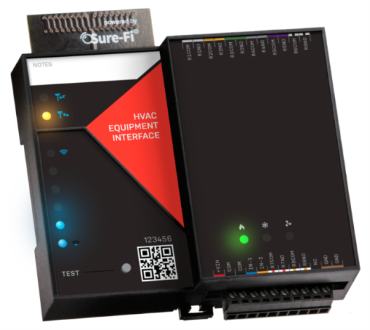
Figure-1: The Sure-Fi HVAC Bridge System wirelessly connects a Thermostat and HVAC Controller:
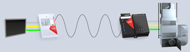
The Sure-Fi SFI-HV200-01 HVAC Bridge System includes two interface units: The Thermostat Interface, and the Equipment Interface. The system is factory paired and is ready for use immediately without any configuration required. The system provides a wireless connection (bridge) from the Thermostat to the HVAC Equipment which eliminates the need for any wire connection between the two.
The Thermostat Interface connects to the Thermostat and is mounted behind the Thermostat or within the wall and communicates the Thermostat’s output states wirelessly to the Equipment Interface, located at and wired to the HVAC Equipment. The Equipment Interface presents the output states from the Thermostat and controls the HVAC Equipment just as the Thermostat would if it were wired directly.
Additionally, the Equipment Interface has two inputs that can be connected to outputs from the HVAC Equipment that are designated to go back to the Thermostat, such as an Equipment/System Monitor (L) function. The Sure-Fi App provides troubleshooting, diagnostics information, and field upgrades.
Features
- Includes a complete wireless solution from the Thermostat to the HVAC Equipment location.
- Works with all standard low-voltage 24VAC systems (Conventional and Heat Pump systems).
- Connects with up to eight outputs from the Thermostat.
- Connects two outputs from the HVAC Equipment back to the Thermostat, ex. Equipment Monitor (L).
- Multiple Equipment Interface units (up to eight) can be paired to one Thermostat Interface unit allowing for one thermostat to control multiple HVAC equipment units.
- General purpose relays that are suitable for multiple applications.
- Signal Strength, Transmit and Receive indicators on Equipment Interface.
- Range: up to 1 mile through obstructions and greater than 50 miles line-of-sight.
General Specifications
| Operating Voltage: | 20 to 30VAC |
| Operating Current (@ 24VAC): | 0.02A (idle), 0.26A (transmit) |
| Operating Power (@ 24VAC): | 6.3VA (peak) |
| Thermostat Interface relays: | Relay Inputs (R1 – R8): 30V max |
| Equipment Interface relays: | Relay inputs (IN 1, IN 2): 30V max || Relay outputs R1 – R5: NO contact only, 1A max. The relay output voltage is equal to the input operating voltage on the unit (the input voltage connected at the +VIN pin on the unit). || Relay outputs R6, R7, R8: FORM A (NO/COM) contacts: 1A 60V max. |
| Range: | Up to 1 mile through obstructions. Greater than 50 miles line-of-sight |
| Operating Temperature: | -40°F to +185°F (-40°C to +85°C) |
| Storage Temperature: | -67°F to +257°F (-55°C to +125°C) |
| Humidity: | 0 to 95% non-condensing |
| Dimensions (Thermostat Int.) : | 4.45”L x 2.75”W x 0.575”H (113mm x 70mm x 15mm) |
| Dimensions (Equipment Int.) : | 4.25”L x 4.20”W x 1.30”H (108mm x 107mm x 33mm) |
| Thermostat Interface Mounting: | Mount to wall direct, mount to single gang box, or place in the wall. |
| Equipment Interface Mounting: | DIN mount or direct mount. 35mm DIN rail (DIN46277-3) |
| Degree of Protection: | IP20 to IEC/EN 60529 |
Radio Transceiver Specifications
| Transmit Power: | 1 Watt (30dBm) |
| Frequency Band: | 902 – 928MHz |
| Channels: | 72 (Frequency hopping) |
| Receiver Sensitivity: | Receiver Sensitivity: -133dBm |
| Link Budget: | 163dB |
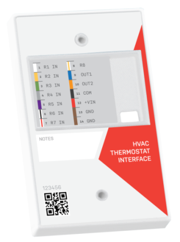
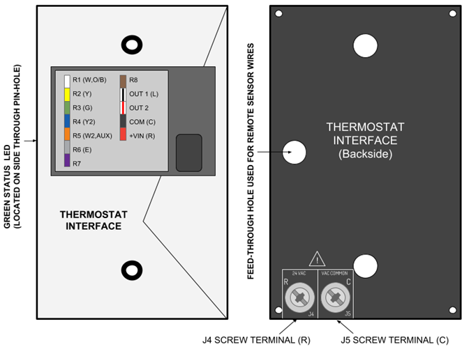
Device Overview: Thermostat Interface
Figure-2: Thermostat Interface overview
Wiring Example: Thermostat Interface
Figure-3: Thermostat Interface wiring example
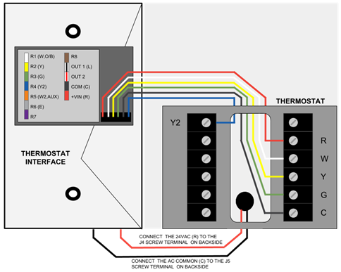
Figure-4: Thermostat Interface wiring examples
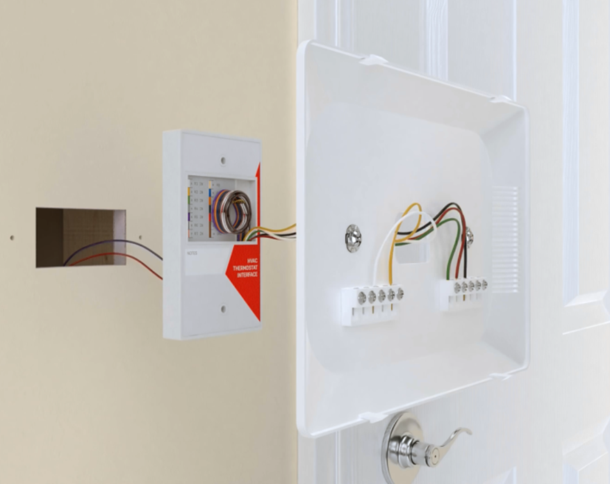
Figure-5: Thermostat Interface wire functions and colors
Thermostat Interface: Wire Functions @amp; Colors
| NAME | WIRE COLOR | DESCRIPTION |
|---|---|---|
| R1 (W,O/B) | WHITE | INPUT CONNECTION FROM THERMOSTAT: CONNECT TO ‘W’ OR ‘O/B’ ON THERMOSTAT |
| R2 (Y) | YELLOW | INPUT CONNECTION FROM THERMOSTAT: CONNECT TO ‘Y’ ON THERMOSTAT |
| R3 (G) | GREEN | INPUT CONNECTION FROM THERMOSTAT: CONNECT TO ‘G’ ON THERMOSTAT |
| R4 (Y2) | BLUE | INPUT CONNECTION FROM THERMOSTAT: CONNECT TO ‘Y2’ ON THERMOSTAT |
| R5 (W2,AUX) | ORANGE | INPUT CONNECTION FROM THERMOSTAT: CONNECT TO ‘W2’ OR ‘AUX’ THERMOSTAT |
| R6 (E) | SLATE | INPUT CONNECTION FROM THERMOSTAT: CONNECT TO ‘E’ OR ANY THERMOSTAT OUTPUT |
| R7 | VIOLET | INPUT CONNECTION FROM THERMOSTAT: CONNECT TO ANY THERMOSTAT OUTPUT |
| R8 | BROWN | INPUT CONNECTION FROM THERMOSTAT: CONNECT TO ANY THERMOSTAT OUTPUT |
| OUT1 (L) | BLACK/WHITE | OUTPUT CONNECTION TO THERMOSTAT: CONNECT TO ‘L’ ON THERMOSTAT IF REQUIRED |
| OUT2 | BLACK/RED | OUTPUT CONNECTION TO THERMOSTAT: AUXILIARY/MISC USE |
| COM (C) | BLACK | (C) AC COMMON POWER WIRE FOR THERMOSTAT, WIRE TO (C) INPUT ON THERMOSTAT |
| +VIN (R) | RED | (R) 24VAC POWER INPUT FOR THERMOSTAT, WIRE TO (R) INPUT ON THERMOSTAT |
Installation Instuctions: Thermostat Interface
The Thermostat Interface is designed to be mounted to the wall just behind the Thermostat or it can be placed inside of the wall by cutting a hole as small as 0.8” x 2.8”.
Thermostat Interface Installation Steps:
- Turn off the 24VAC power if present.
- Remove the Thermostat and Thermostat Base plate. REMOVE ALL EXISTING THERMOSTAT WIRES FROM THE THERMOSTAT BASE PLATE. Figure-7.
- Bend back all wires that will not be used. Figure-8.
- The Thermostat Interface powers the Thermostat. The Thermostat Interface can be powered by a 24VAC Transformer or with the 24VAC, “R” and “COMMOM” wire from the HVAC Equipment Control board.
- Connect the 24VAC power to the ’J4’ and ’J5’ terminals on the backside of the Interface. Figure-9.
- Following the Wire Functions @amp; Color Chart in Figure-6 (page-9), select the wires needed. Figure-10.
- Feed the wires through the back of the Thermostat base plate to the Thermostat block. Figure-11.
- Replace the Thermostat face. If the Thermostat Interface is going to be placed within the wall, leave it outside of the wall until the Equipment Interface is installed and all system functions have been tested.
- After the system has be tested for proper functionality, mount the Thermostat Interface and the Thermostat to the wall, or if the Thermostat Interface is being placed within the wall, push the Thermostat Interface in to the wall and mount the Thermostat. Note: be sure to fill any holes or gaps in the wall to prevent air movement which can affect the Thermostat temperature sensor readings.
Figure-6: Remove Thermostat Face and Base Plate.
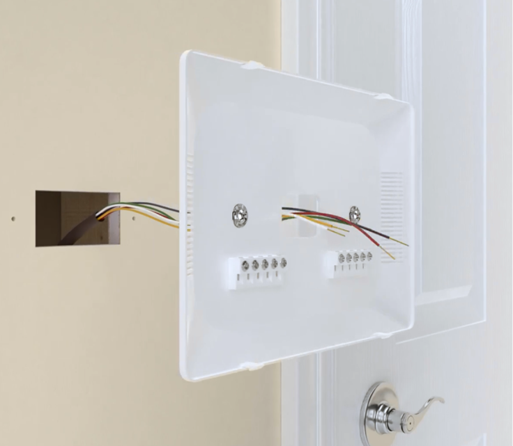
Figure-7: Secure all unused Thermostat wires.
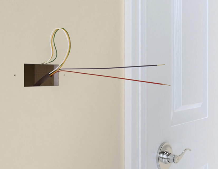
Figure-8: Connecting 24VAC: The 24VAC (R) and (C) wires are shown connected to the J4 and J5 screw terminals. NOTE: The Thermostat Interface feeds the 24VAC to the Thermostat. Do not use a jumper wire.
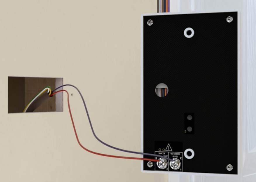
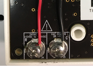
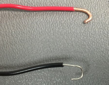
Figure-9: Following the Wire Function @amp; Color Chart in Figure-6, select the wires needed for the Thermostat functions required.
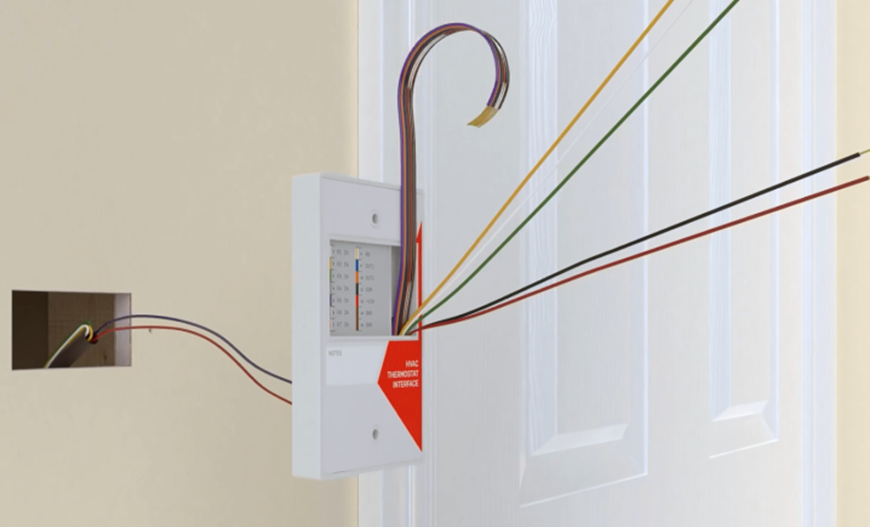
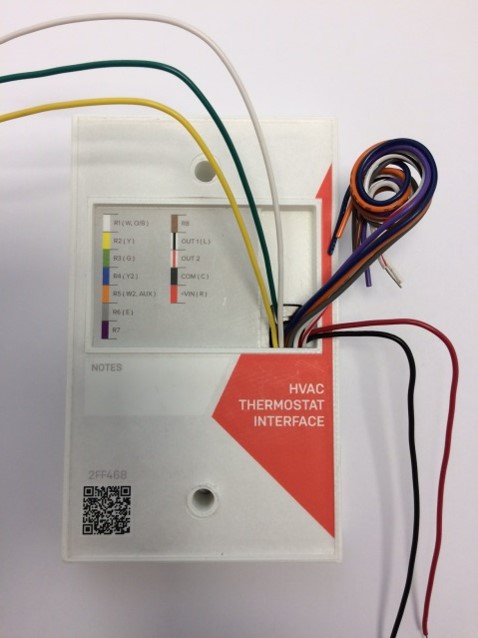
Figure-10: Feed the wires through the back of the Thermostat base plate and connect to the Thermostat terminal block.
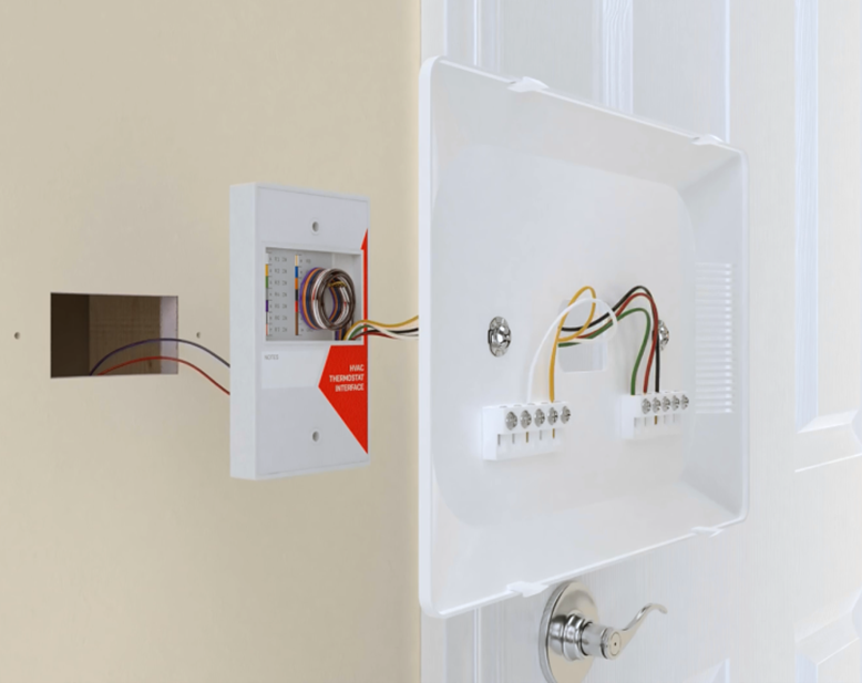
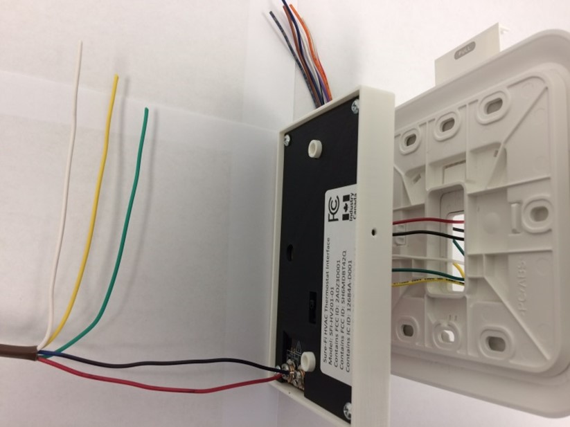
Figure-11: Replace the Thermostat face. Do not insert the Thermostat Interface into the wall until the Equipment Interface is installed and all system functions have been tested.
Providing Power to the Thermostat Interface:

Disconnect the 24VAC power before connecting the wires to the Thermostat Interface. Do not turn on the 24VAC power until all of the wiring to the Thermostat is complete.
Connect the wires for the 24VAC input power to the two screw-terminals that are on the backside of Thermostat Interface. These two connectors are labeled ’J4’ and ’J5’. Connect the Red (R) wire (24VAC positive) to the ’J4’ screw terminal, and connect the Black (C) (AC COMMON) wire to the ’J5’ screw terminal. For the most secure connection, it is recommended to place a half-circle bend in each wire (see Figure 9) before securing in to the screw terminal. Ensure that the two scew terminals are tightened adequately to hold the wires in place when moved, pulled, etc. Also be sure that the screws are tightned down enough to provide clearance behind the case so that they are not able to come in to contact with the mounting surface, particularly if mounting to a metal surface.
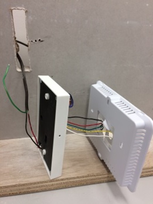
Wiring the Thermostat Interface to the Thermostat:
The flying lead wire harness on the Thermostat Interface contains twelve wires and is used to wire the Thermostat Interface to the Thermostat. The wires are solid 24 Awg and are approximately 5.5” long. Use the color code chart on the Label of the Thermostat Interface to select the wires that are needed for the Thermostat functions that are required. Tightly coil up the unused wires (may need to cut them shorter) and press them into the recessed area of Thermostat Interface case.
Wiring a Remote Sensor to the Thermostat:
To wire a Thermostat to remote sensors (if used), route the remote sensor wires through the hole in the back side of the Thermostat Interface and out through the front to the Thermostat (see Figure 2).
PROCEDE TO INSTALLING THE EQUIPMENT INTERFACE
Device Overview: Equipment Interface
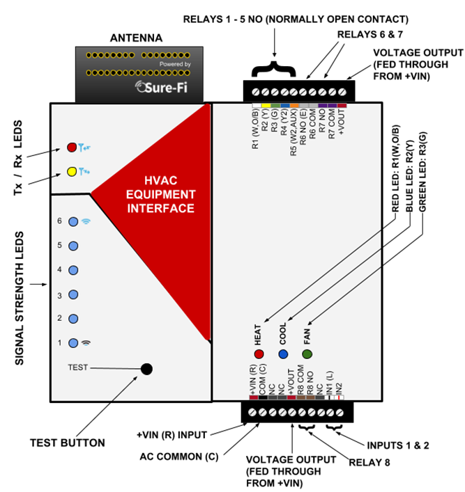
Figure 12: Equipment Interface overview.
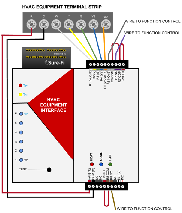
Wiring Examples: Equipment Interface
Figure 13: Equipment Interface wiring example.
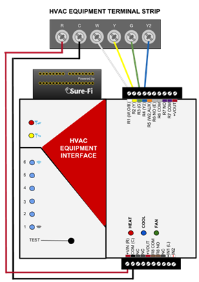
Figure-13: Equipment Interface wired and mounted
Bottom edge connector: Equipment Interface
Figure 15: Equipment Interface Bottom Edge Connector (See Figure 12 for reference).
| POSITION | NAME | DESCRIPTION |
|---|---|---|
| 1 (left) | +VIN (R) | (R) 20 TO 30 VAC POSITIVE INPUT POWER |
| 2 | COM (C) | (C) AC COMMON |
| 3 | NC | NO CONNECTION |
| 4 | NC | NO CONNECTION |
| 5 | +VOUT | USE FOR OUTPUT VOLTAGE FOR R8 COM, FED DIRECTLY FROM THE +VIN VOLTAGE INPUT |
| 6 | R8 COM | RELAY 8 COMMON CONTACT |
| 7 | R8 NO | RELAY 8 NORMALLY-OPEN CONTACT |
| 8 | NC | NO CONNECTION |
| 9 | IN1 (L) | (L) EQUIPMENT MONITOR INPUT. CONNECT TO HVAC EQUIPMENT MONITIOR IF USED |
| 10 (right) | IN2 | AUXILIARY/SPARE INPUT |
Top Edge connector: Equipment Interface
Figure 16: Equipment Interface Top Edge Connector (See Figure 13 for reference).
| POSTION | NAME | DESCRIPTION |
|---|---|---|
| 1 (Right) | +VOUT | USE FOR OUTPUT VOLTAGE, FED DIRECTLY FROM THE +VIN VOLTAGE INPUT |
| 2 | R7 COM | RELAY 7 COMMON CONTACT |
| 3 | R7 NO | RELAY 7 NORMALLY-OPEN CONTACT |
| 4 | R6 COM | RELAY 6 COMMON CONTACT |
| 5 | R6 NO (E) | RELAY 6 NORMALLY-OPEN CONTACT |
| 6 | R5 (W2,AUX) | RELAY 5 NORMALLY-OPEN CONTACT |
| 7 | R4 (Y2) | RELAY 4 NORMALLY-OPEN CONTACT |
| 8 | R3 (G) | RELAY 3 NORMALLY-OPEN CONTACT |
| 9 | R2 (Y) | RELAY 2 NORMALLY-OPEN CONTACT |
| 10 (left) | R1 (W,O/B) | RELAY 1 NORMALLY-OPEN CONTACT |
Installation Instuctions: Equipment Interface
The Equipment Interface should be mounted close to the HVAC Control board and can be mounted within the metal cabinet with the HVAC control board.
Equipment Interface Installation Steps:
- Turn off the main power to the HVAC/Furnace unit and check that the 24VAC is also turned off.
- Mount the Equipment Interface next to the HVAC Control board.
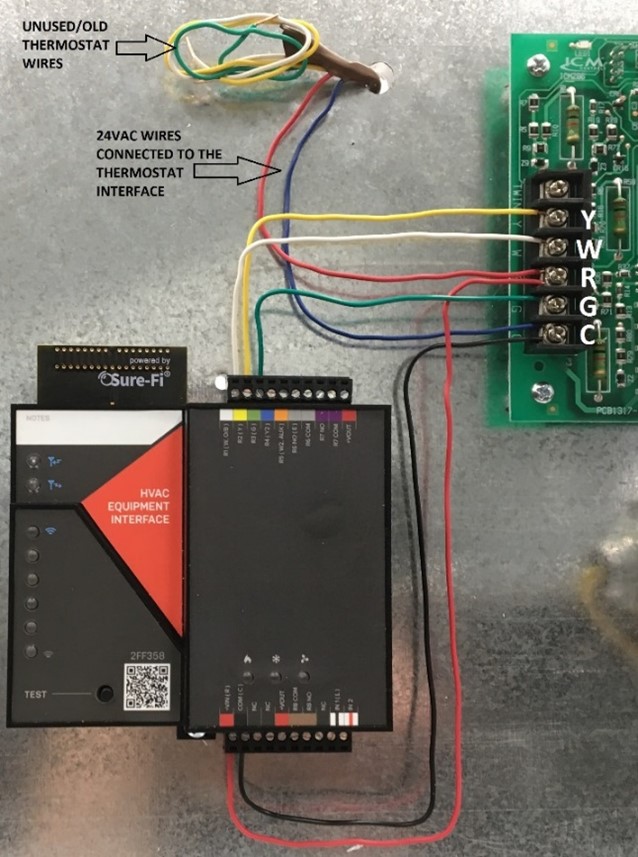
- Wire 24VAC power from the HVAC Control board to the Equipment Interface.
- Wire the required Thermostat functions from the Equipment Interface to the HVAC Control board. These must be wired in the same way that the Thermostat Interface is wired to the Thermostat such that each function corresponds to the same function on each unit, ie W,Y,G, etc.
- If the Thermostat Interface is to be powered from the 24VAC on the HVAC Control board then connect the ends of the two Thermostat wires that were connected to the J4 and J5 screw terminals on the back of the Thermostat Interface to the 24VAC terminals on the HVAC Control board.
- Turn the main power back on the HVAC/Furnace unit.
- Check that the Equipment Interface is powered and is communicating with the Thermostat Interface unit by performing a Range-Test. To start a Range-Test, press and quickly release the Test button on the Equipment Interface.
- Test all the required Thermostat functions to ensure that each function that is set on the Thermostat corresponds correctly with each activated state on the HVAC Equipment.
Providing Power to the Equipment Interface:
Turn off the 24VAC power before connecting to the Equipment Interface. Do not turn on the 24VAC power until all of the wiring between the Equipment Interface and the HVAC Equipment is complete.
Connect the wires for the 24VAC input power to the +VIN (R) and COM (C) terminals of the Equipment Interface (see Figures 12, 13, @amp; 14).
Wiring the Equipment Interface to the HVAC Equipment:
See Figures 12, 13, @amp; 14 for reference. The Equipment Interface has eight relay outputs and two inputs that can be used with the HVAC Equipment. Using solid wire (24 Awg to 18 Awg), wire the required connections from the 10-position terminal plug(s) to the corresponding HVAC Control board terminal.
Relay 1 through Relay 5:
Relay 1 through Relay 5 have only the NO (Normally Open) relay contact available on the terminal connector. The relay COMMON contact of Relay 1 through Relay 5 is internally connected to the +VIN (R) power input such that when the relay is energized, the +VIN (R) will then be present on the relay NO contact. This allows for simplified wiring of Relays 1 through 5.
Relay 6 through 8 (see Figure 23):
Relays 6, 7, and 8 have the NO (Normally Open) and the COMMON contacts (FORM A) available on the terminal connector. If any of these relays are to be used, the COMMON contact for the relay will have to be connected to a voltage source that is required for the device that is being controlled with the relay. A typical connection method that can be used If the voltage that is on +VIN (R) terminal is adequate for the relay control function, is to use a jumper wire to connect the +VOUT (on the right side of the top connector) to the R6 COM and/or the R7 COM to use either of those two relays. If Relay 8 is being used, a jumper wire from the +VOUT that is next to the R8 COM terminal position, can be placed between this +VOUT position to the R8 COM terminal position.
IN1 (L) and IN2:
The IN1 (L) and IN2 on the bottom terminal connector are wired to outputs from the HVAC Equipment that are normally connected back to the Thermostat, for example an Equipment/System Monitor connections.
Equipment Interface: Test (Range Test) Push Button
Range Test: Pressing and releasing the ‘Test’ button quickly initiates the Range Test. The Range Test feature is used to test the signal strength of the radio transceiver between the Equipment and Thermostat Interfaces. The result of the Range Test is displayed on the six blue LEDs, these are labeled ‘Signal Strength LEDS (1 – 6)’ in Figure 13. Maximum signal strength is indicated when LEDs 1 through 6 all flash ON momentarily, and minimum signal strength is indicated when only LED 1 flashes ON.
Thermostat Interface: Status LED (Refer to Figure 2)
- Status LED: The Green Status LED is located on the side of the Thermostat Interface unit. The LED is mounted to the board and is visible through a small hole in the side of the case. The LED uses flashcodes to show system status and can be used to assist with troubleshooting.
Equipment Interface: LEDS (Refer to Figure 12)
- Rx LED: The Rx LED will flash once briefly when a Sure-Fi radio transmission is received.
- Tx LED: The Tx LED will flash once briefly upon a radio transmission.
- Signal Strength LEDs: These six LEDs display the received signal strength. Maximum signal strength is indicated when LEDs 1 through 6 all flash ON. Minimum signal strength is indicated when only LED 1 flashes ON.
- Heat (Red), Cool (Blue), and Fan (Green) LED’s: The red ‘Heat’ LED will light when the Equipment Interface R1(W,O/B) output is ON. The blue ‘Cool’ LED will light when the Equipment Interface R2(Y) output is ON. The green ‘Fan’ LED will light when the Equipment Interface R3(G) output is ON.

Equipment Interface: Antenna
The radio antenna is created using copper traces on both sides of the PC Board. Use caution when handling and mounting the unit to ensure that no damage (scratches, etc) occurs to the PC Board/Antenna. Additionally, for best performance, keep cables and wiring away from the antenna and mount the unit oriented with the antenna upwards.
Equipment Interface: Connectors
The top and bottom connectors are 10-position, 3.5mm EURO type. The mating plug is Molex pn 39500-0010. Wire Range: 16 to 30AWG. Wire strip length 0.250”. Recommended screwdriver: slotted blade 0.98” width. To install a wire, turn the screw counter-clockwise 3 or 4 turns, insert the wire and hold in place while tightening the screw. When complete, pull on the wire to ensure that it is tightened adequately.
Mounting Orientation and Guidelines
Thermostat Interface Unit:
The Thermostat Interface unit can be mounted to the wall behind the Thermostat in the vertical or horizontal orientation or it can be placed within the wall. The hole spacing is 3.25” which will fit a single-gang electrical box if required. The hole is sized for up to a #8 screw size.
The Equipment Interface Unit:
The Equipment Interface unit will function optimally when oriented with the Antenna positioned at top side of the unit and mounted vertically (see Figure 19). For the best RF range, route all wires and cables away from the Antenna and avoid having any wires crossing directly over the Equipment Interface unit.
There are two common methods for mounting the Equipment Interface Unit:
DIN Rail mount:
DIN rail mounting allows the unit to easily clip and unclip from the DIN rail. Attach a piece (minimum 4” length) of 35mm type DIN rail to the wall and then snap the unit to the DIN rail or slide it on from the end. The unit will snap in to place by putting the top retaining tabs on to the DIN rail first, then pressing the bottom on to the DIN rail until it snaps in to place, the bottom DIN clip may need to be pressed upward to seat into its locked position. To remove the unit from the DIN rail, use a small screwdriver, insert in to the bottom DIN rail clip and pull gently down and outward until the unit releases from the DIN rail.
Screw mount:
The DIN rail clips on the base of the enclosure case can be snapped outward to allow for screw mounting of the case. Mount using only the single bottom DIN clip and the top DIN clip that is located on the side below the 10-position connector. Do not use the DIN clip located behind the antenna. See Figures 20 – 24.
If mounting the unit to metal, take note that metal shavings that are created can drop into the unit and damage the electronics. To avoid any metal shavings from dropping down in to the case, it is recommended to remove the top DIN clip completely from the base and secure it to the wall first, then slide the case on to the DIN clip. The second screw can then be secured through the bottom DIN clip without removing the clip. #8 self-drilling screws are recommended. Do not use any screw that is larger than a #8 size.
Figure 17: The two DIN Clips are shown pressed outward for direct screw mounting.
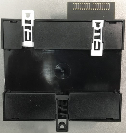
Figure 18: Top DIN Clip is shown removed from the base to mount the DIN clip separately.
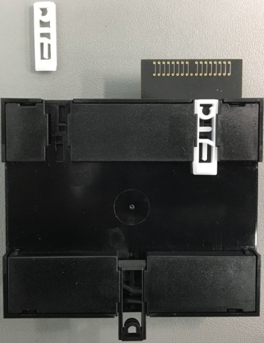
Figure 19: Top DIN Clip is shown mounted first to avoid any metal shavings from dropping in to the case.
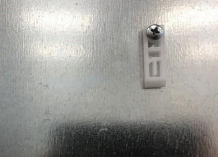
Figure 20: The DIN clip on the top is shown secured with a #8 screw and the base reconnected to the DIN clip.
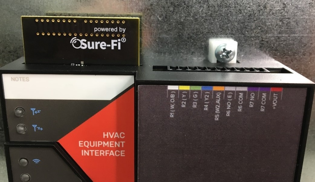
Figure 21: The DIN clip on the bottom is shown secured with the #8 screw:
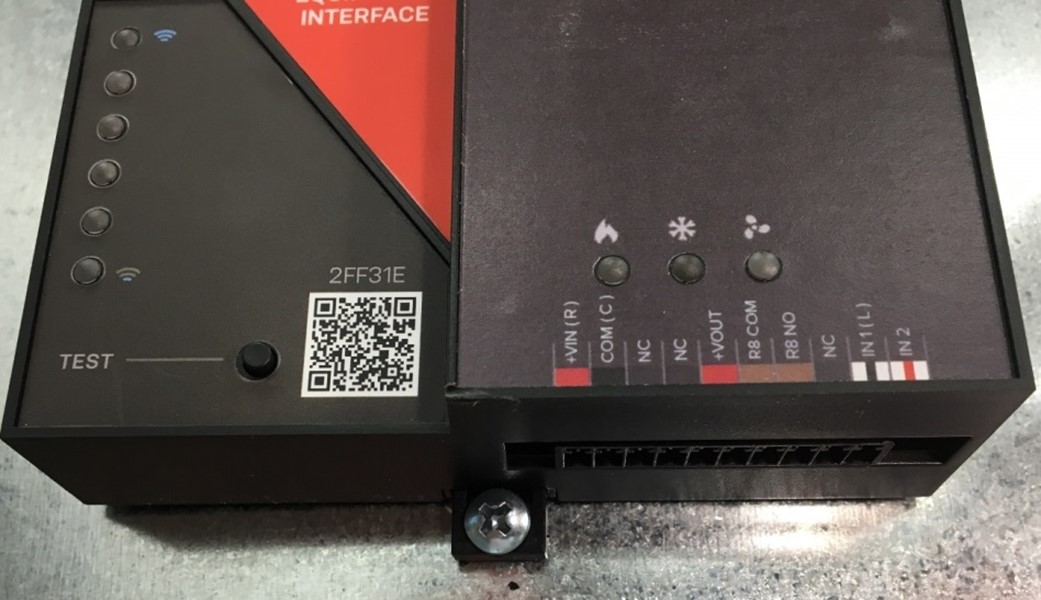
Figure 22: Equipment Interface with the relay COM of R6, R7, and R8 shown wired to +VOUT
Troubleshooting
If the Thermostat does not appear to be communicating with the Equipment Interface:
Range Test:
Press and release the ‘Test’ button on the Equipment Interface unit and observe the six Signal Strength LEDs. If any of blue LED 1 through LED 6 LEDs light up (flash), then the radio transmission between the two units was successful which means that the two units are powered, operating, and can transmit and receive properly. Perform the Range Test several times to ensure communications and note how many of the blues LEDs are lighting up.
Next, check the following:
- Check for proper power input (20 to 30VAC)
- Ensure that all wiring is correct
- Check that all wiring connections are securely connected
- Check that the wire insulation is stripped back far enough and is not interfering with the electrical connection in the pluggable terminal connector.
- Ensure that the 10-position pluggable terminal connectors are plugged in and seated down all the way.
- Ensure that the 10-position pluggable terminal connectors are not offset to left or to the right.
Sure-Fi APP:
The Sure-Fi APP allows for firmware updates and configuration as well as for some diagnostics and troubleshooting information. The APP is continually being updated to provide for more information and features and to improve its ease of use. To download, search for ‘Sure-Fi’ and then download and install. The key features of the APP are:
- Field firmware updates
- Setting default Relay output values upon a set timeout interval (in increments of the Heartbeat time)
- Changing the system Heartbeat time
- Diagnostics and Troubleshooting
- Access to documentation (Operators Manual, Application Notes, Reference documents, etc.)
- Pairing multiple Equipment Interface units to one Thermostat Interface unit
FCC and Industry Canada Regulatory Statements
FCC
This device complies with part 15 of the FCC rules. Operation is subject to the following two conditions: (1) This device may not cause harmful interference, and (2) this device must accept any interference received, including interference that may cause undesired operation. Any changes or modifications not expressly approved by manufacturer could void the user’s authority to operate the equipment.
IMPORTANT! Any changes or modifications not expressly approved by the party responsible for compliance could void the user’s authority to operate this equipment.
Industry Canada
This device complies with Industry Canada license-exempt RSS standard(s). Operation is subject to the following two conditions: (1) this device may not cause interference, and (2) this device must accept any interference, including interference that may cause undesired operation of the device.
Le présent appareil est conforme aux CNR d’Industrie Canada applicables aux appareils radio exempts de licence. L’exploitation est autorisée aux deux conditions suivantes: (1) l’appareil ne doit pas produire de brouillage, et (2) l’utilisateur de l’appareil doit accepter tout brouillage radioélectrique subi, meme si le brouillage est susceptible d’en compromettre le fonctionnement.
IMPORTANT! Tous les changements ou modifications pas expressément approuvés par la partie responsable de la conformité ont pu vider l’autorité de l’utilisateur pour actioner cet équipment.
47 CFR 15.105- FCC
NOTE: This equipment has been tested and found to comply with the limits for a Class B digital device, pursuant to part 15 of the FCC Rules. These limits are designed to provide reasonable protection against harmful interference in a residential installation. This equipment generates, uses and can radiate radio frequency energy and, if not installed and used in accordance with the instructions, may cause harmful interference to radio communications. However, there is no guarantee that interference will not occur in a particular installation. If this equipment does cause harmful interference to radio or television reception, which can be determined by turning the equipment off and on, the user is encouraged to try to correct the interference by one or more of the following measures:
- Reorient or relocate the receiving antenna.
- Increase the separation between the equipment and receiver.
- Connect the equipment into an outlet on a circuit different from that to which the receiver is connected.
- Consult the dealer or an experienced radio/ TV technician for help.
This Class B digital apparatus complies with Canadian ICES-003.
Cet appareil numérique de la classe B est conforme à la norme NMB-003 du Canada
FCC Radiation Exposure Statement
This equipment complies with FCC radiation exposure limits set forth for an uncontrolled environment. This equipment should be installed and operated with minimum distance 20cm between the radiator and your body.
Important Note:
Radiation Exposure Statement:
This equipment complies with IC radiation exposure limits set forth for an uncontrolled environment. This equipment should be installed and operated with minimum distance 20cm between the radiator and your body.
Note Importante: (Pour l’utilisation de dispositifs mobiles) Declaration d’exposition aus radiations:
Cet équipement est conforme aux limites d´exposition aux rayonnements IC établies pour un environnement non contrôlé. Cet équipment doit être installé et utilisé avec un mimimum de 20 cm de distance entre la source de rayonnement et votre corps.
Warranty
The warranty period of this product is 5 years from purchase date, beginning from first power up of the device after purchase. During this period, if the product does not operate correctly, due to a defective component, the product will be repaired or replaced at the sole discretion of Sure-Fi, Inc. This warranty does not extend to the product casing which can be damaged by conditions outside of the control of Sure-Fi, Inc.
EXCEPT AS SET FORTH ABOVE, SURE-FI, INC. MAKES NO WARRANTIES REGARDING THE GOODS, EXPRESS OR IMPLIED, INCLUDING WARRANTY OF MERCHANTABILITY OR WARRANTY OF FITNESS FOR A PARTICULAR PURPOSE. BUYER MAKES NO RELIANCE ON ANY REPRESENTATION OF SURE-FI, INC., EXPRESS OR IMPLIED, WITH REGARD TO THE GOODS AND ACCEPTS THEM “AS-IS/WHERE-IS”. SURE-FI, INC SELLS THE GOODS TO BUYER ON CONDITION THAT SURE-FI, INC. WILL HAVE NO LIABILITY OF ANY KIND AS A RESULT OF THE SALE. BUYER AGREES THAT SURE-FI, INC. SHALL HAVE NO LIABILITY FOR DAMAGES OF ANY KIND, WHETHER DIRECT, INCIDENTAL OR CONSEQUENTIAL DAMAGES, INCLUDING INJURIES TO PERSONS OR PROPERTY, TO BUYER, ITS EMPLOYEES OR AGENTS, AS A RESULT OF THE SALE. BUYER ALSO AGREES TO HOLD SURE-FI, INC. HARMLESS FROM ANY CLAIMS BUYER, OR ANY THIRD PARTY, MAY HAVE AS A RESULT OF BUYER’S USE OR DISPOSAL OF THE GOODS. BUYER HAS READ THIS DISCLAIMER AND AGREES WITH ITS TERMS IN CONSIDERATION OF RECEIVING THE GOODS.